 |
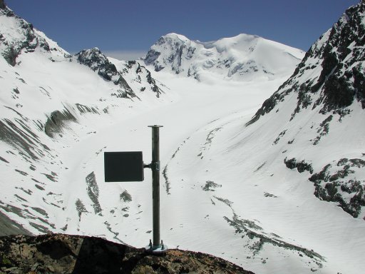
The first step is to calculate the visible portion of the digital elevation model from the point of view of the camera. For this computation we need to know the exact position of the observer (camera), and the direction and field of view. The first datum is read from a GPS and altimeter at the time of taking the photograph. The second information is derived from the actual photograph itself, by identifying precisely the location of the target or central pixel of the image. It could also be derived from accurate information of the azimuth and elevation of the camera direction of sight by using a phototheodolite, for example. Finally, the field of view is derived from the focal length and the dimensions of the film.
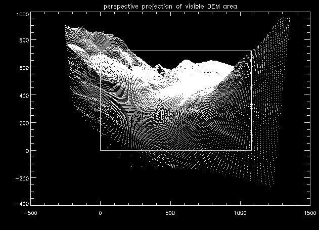
Once visibility has been calculated we apply a viewing transformation that maps points in the world coordinate system (that of the DEM) to points in the camera coordinate system, representing the viewing geometry of the camera in three-dimensional space, as shown in figure 1. A viewing transformation is parameterised by a viewing direction vector N, a vector V indicating which way is up, a vector U positive in the direction of the X-axis and a viewing position C ( e.g. Fiume, 1989). This is a standard procedure for obtaining perspective views in computer graphics (e.g. Foley et al., 1990). Firstly we apply a translation transformation to set the origin at C, the camera position.
|
The viewing transformation is then completed by multiplying the result of this translation by the following transformation matrix, that rotates the translated coordinates according to the viewing coordinate axis:
 |
where f is the camera focal length.
 |
 |
 |
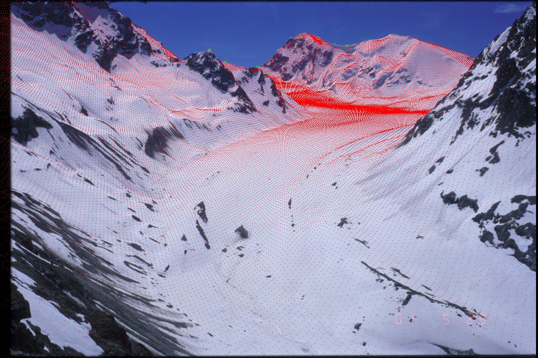 |
Green dots are ground control points and red dots the superimposed scaled perspective projection of grid cells in the original DEM.